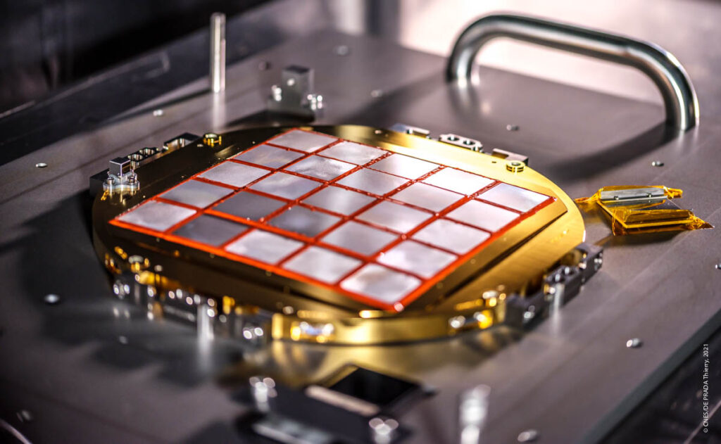
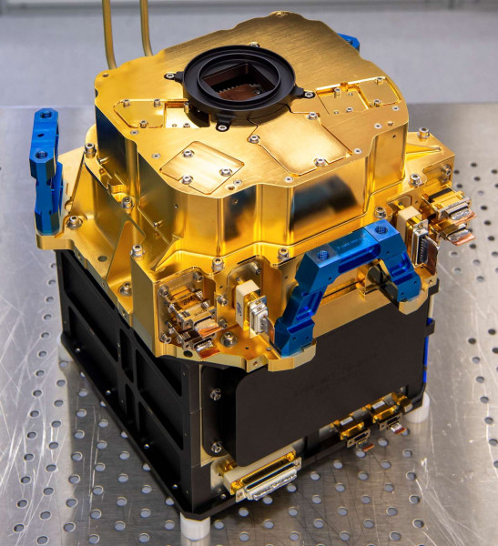
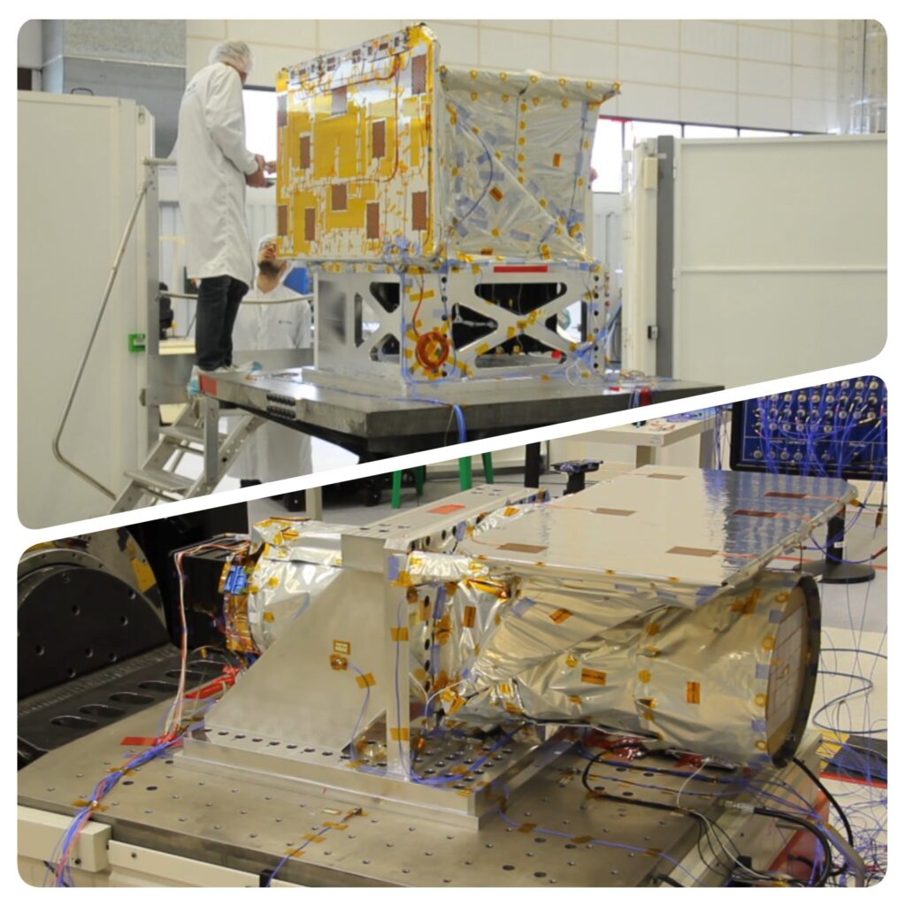
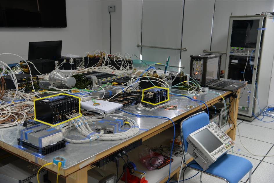
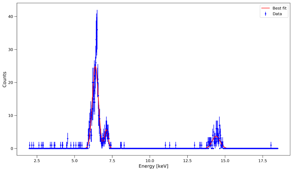
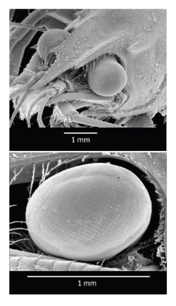
Menu Close

The MXT telescope optics, an original device inspired by lobster eyes to ensure a large field of view, have just been delivered by the CNES teams at the beginning of May 2021. This revolutionary optics, placed at the entrance of the MXT telescope, will allow to collect the X-rays in a field of 1 square degree on the sky (i.e. 4 times the apparent surface of the Sun) and direct them towards the MXT camera at the focus of the telescope.

The optics of the MXT telescope of the SVOM satellite. Credits: CNES / DE T. PRADA, 2021

The optics is composed of 25 plates arranged in a mosaic. Inspired by the faceted eyes of crustaceans, each plate contains approximately 600,000 “facets” of glass of only 40 microns per side. This set constitutes the MXT’s micro-channel concentrator. This optics required high-precision glasswork carried out by the company Photonis. According to François Gonzalez, SVOM project manager at CNES, “Making regular micro-channels of this size in glass has been a big challenge. The industrial process requires more than 50 manufacturing steps, each as complex and delicate as the next ”.
The plates were then integrated at the University of Leicester (UK) on a slightly convex aluminum frame, fitted with heaters for thermal control and with a system of magnets to deflect the charged particles. They are coated with iridium to increase their x-ray reflectivity and the entrance surface is coated with a thin layer of aluminum to block visible light.

The optic positioned at the entrance of the MXT telescope. Credits: CNES / DE T. PRADA, 2021.

This extremely innovative optics has allowed a remarkable gain of weight since the assembly weighs less than 2 kg, against several tens of kg for similar instruments in space missions such as SWIFT and XMM-Newton. During 2021, this optics will be assembled on the MXT telescope structure and the entire MXT telescope (optics and camera) will undergo testing and final calibration which will be performed at the MPE X-ray Panter facility in Munich (Germany) before shipping to China scheduled for late 2021.

Related Posts

The X-ray camera, intended to be placed at the focus of the MXT (Microchannel X-ray Telescope), has just been assembled and delivered to CNES by CEA teams in May 2021.
This high-tech prototype is particularly compact and innovative. It incorporates in a very limited volume, a detector with its electronic control system, an active thermal control and a filter wheel. The detector consists of a monolithic block divided into 256 × 256 pixels. It is integrated on a ceramic plate, surrounded by a shielding to reduce the impact of cosmic radiation on the detector. It is also equipped with a system of three thermoelectric coolers which keeps the temperature of the detector plane between -75 and -60 ° C. The detector assembly is inserted into a housing, which also contains a filter wheel, used for calibration and protection.

The MXT's X-ray camera (0.2 to 10 keV) integrates a 256 × 256 element pnCCD detector, its electronic control system as well as three thermoelectric coolers to maintain the temperature between -75 and -60 ° C) and a filter wheel. DAP / Irfu-CEA credits
The MXT’s X-ray camera (0.2 to 10 keV) integrates a 256 × 256 element pnCCD detector, its electronic control system as well as three thermoelectric coolers to maintain the temperature between -75 and -60 ° C) and a filter wheel. Copyright DAP / Irfu-CEA

The video below illustrates the different stages of camera assembly.

The camera project, which started in 2013, was carried out in collaboration with the French Space Agency (CNES). The pnCCD type detector and its proximity electronics (CAMEX) were provided by the Max Planck Institut für Extraterrestische Physik (MPE). To carry out in-depth testing, three different models of the camera have been built over the years: a structural and thermal model (STM), a performance model (PM) which allowed to validate the complete detection chain and a shock (SM) to test its resistance, before producing the final model called “Proto flight model (PFM)”. All these models and their sub-systems were designed and integrated at the CEA and manufactured by the CEA or its subcontractors. Their development involved a team of more than 20 people. The latest PFM model was produced despite the pandemic COVID-19 crisis, thanks to the strong motivation of the technicians, engineers and scientists involved in the project.

Left: the technical team of the camera in the clean room at DAp / CEA. Right: the fully assembled MXT camera.

The next steps in 2021 will be the assembly and testing of the entire MXT telescope and its final calibration which will be performed at the MPE X-ray Panter facility in Munich. The CEA MXT team will support CNES during all these tests. At the end of this test campaign in November 2021, the MXT telescope will be shipped to China for final integration on the SVOM satellite, scheduled for launch before the end of 2023.

Related Posts

The MXT Performance Model successfully tested at MPE Panter X-ray beam facility

A campaign dedicated to the verification and validation of the performance of the different modules (optics, camera, electronics) of SVOM’s MXT telescope has been successfully conducted at the Panter X-ray beam facility located near Munich. The results validate the concept of the MXT instrument and push the MXT project to new steps before its installation on the SVOM satellite platform in 2021.

In February 2020, the MXT teams (CNES, CEA, University of Leicester, MPE and IJCLAb-Orsay, gathered at Panter X-ray testing facility near Munich, in order to perform a full end-to-end test of the MXT Performance Model. The telescope, composed by the optics qualification model (QM), the camera performance model (PM) had been integrated at CNES Toulouse and shipped to Panter at the end of January. All the elements were flight representative in terms of performance (except for the focal length, that is slightly shorter than the flight model one) and allowed to validate for the first time a complete system composed of a “Lobster-Eye” telescope in a narrow field configuration.

The MXT Team is celebrating the end of the Performance Tests campaign in Panter!

After setting up and validating the thermal environment, the performance tests took place for two weeks, during which scientists and engineers were able to test different aspects of the telescope. 170 science runs have been acquired in order to answer to the planned scientific goals.

MXT PM subsystem ready to be integrated at CNES Toulouse: on the top the MXT optics, at the bottom right the camera, and at bottom left the structural tube.

The properties of the MXT point spread function (PSF) have been measured at different positions and energies over the entire operational range (0.2-10 keV). At 1.5 keV the PSF FWHM was measured to be 9.6 arc min, with a negligible level of vignetting over the entire field of view.

Left: MXT PSF obtained with a C-K source (0.28 keV). Right: MXT PSF obtained with a Ge-K source (9.88 keV).

The Panter tests allowed us also to measure the spectral performance of the telescope over its entire energy range: the MXT camera has confirmed to be a low-noise system with state-of-the-art spectral capabilities. As an example, an Al-K source spectrum is shown (Fig. below). The energy resolution for single events measured at the MXT nominal operating temperature (~-70°C) is 78 eV, smaller than the instrument requirement of 80 eV. We were also able to explore different thermal configurations, and measure their impact on the telescope performance.

Al-K (1.49 keV) single events spectrum obtained with MXT during Panter tests

The next steps for the MXT telescope are the completion of the flight model sub-systems, their integration and the final end-to-end tests that will take place in Panter in about one year from now, just before shipping the telescope to China for final integration of the SVOM platform.

Related Posts

Final step before the delivery of the STM telescopes of the French SVOM payload

This is the last step for our models before delivery in China, the CNES teams have just carried out environmental tests on 2 models of the ECLAIRs and MXT telescopes. The objective of these tests is to “qualify” (demonstrate) with sufficient margin the telescopes’ ability to withstand launch conditions and then the hostile space environment throughout the mission.

The purpose of these tests is not to test flight equipment but to test simplified models that are mechanically and thermally representative of future instruments. We are talking about STM models for Structural and Thermal Model. These STM models are defined in such a way as to accurately reproduce the mechanical (same interfaces, same mass, same manufacturing processes, same materials) and thermal (same power dissipation, same thermal leaks) behaviour of flight instruments. However, they are not equipped with detectors or electronic subsystems.

The tests of each telescope were carried out in 3 stages:

  • Mechanical vibration tests: the telescope is installed on a shaker, a kind of large loudspeaker that will shake the instrument energetically in various directions and at different oscillation frequencies. Two types of solicitations are applied, sinusoidal and random solicitations. Sinusoidal tests are mainly used to quantify the behaviour and strength of the instrument and to confirm simulation results. Here the movement applied to the instrument takes the form of an oscillation whose frequency increases with time and whose amplitude is calculated in such a way as to reproduce the forces to which the instrument must be able to resist. The randomized test is intended to be much more representative of what the instrument will undergo at launch.
  • Mechanical impact tests: the instrument is installed on an “impact table” equipped with pyrotechnic devices. These devices are like miniature cannons. The firing of a small explosive charge propels a metal mass that hits the table. The charge and metal mass are dimensioned to obtain a shock representative of what the instrument must withstand, for example when separating from the launcher or when opening the solar panels.
  • Thermal vacuum tests: the telescope is installed here in a tank in which vacuum is made. Various devices, liquid nitrogen-cooled screens and electric heaters allow to expose the instrument to the most extreme temperatures, hot or cold, that it will face in orbit.

The stress levels applied to the instruments during these tests are deliberately higher than those that will be experienced in flight. This makes it possible to cover both the uncertainties on the knowledge of the mechanical and thermal environment experienced throughout the mission and the manufacturing gaps between the STM models and the flight models.

The environmental tests of the STM models of the ECLAIRs and MXT telescopes were carried out at Airbus Defence & Space, which has all the necessary resources on the same technical platform. A CNES team of 30 people mobilized this summer by juggling the availability of test resources in order to be ready for the meeting scheduled with our Chinese partners. Everyone’s efforts have made it possible to achieve all the objectives set and to deliver the equipment on time.

Structural and Thermal Model of the ECLAIRs telescope

Structural and Thermal Model of the MXT telescope


Related Posts

From mid-February to mid-March 2019, the Chinese and French SVOM project teams carried out the first coupling of the ECLAIRs and MXT instrument calculators with the SVOM satellite. The objective of these tests was to validate the electrical interfaces between the French equipment and the rest of the satellite.

On the French side, the ECLAIRs and MXT calculators are represented by their Engineering and Qualification Models (EQM). These models are, for their material part, fully representative of future flight models. On the other hand, the software part is limited to the command / control part interfaced with the satellite. At this stage, no science is implanted in the calculators. On the Chinese side, the satellite is represented by all the electronic boxes of the platform’s various equipment and payload, all assembled on a table, in a “Flat Sat” configuration.

SVOM Flat Sat with ECLAIRs (left) and MXT (right) boxes

The test sequence was carried out in two stages. In a first phase, the teams coupled the calculators electrically with the rest of the Flat Sat. During this step, all connectors, harnesses and electrical signals must be checked before gradually connecting the power supplies and then the various communication channels. At the end of this first phase, the French computers are connected to the satellite, powered by it and are able to communicate with the payload computer. The second phase can begin. The aim is to validate the proper functioning of the entire payload. Several test sequences are carried out to validate the different communication channels (Telemetry, remote controls and alert messages) and operational programming (Alert sequence, instrument mode management, South Atlantic Anomaly management, configuration table management).

This first meeting between Chinese and French equipment was also the opportunity to test the assembly of French boxes on the future satellite model used to qualify SVOM. This confirmed that the holes fall in front of the holes and that everything was properly installed.

Installation of the MXT box on the +Y wall of the SVOM QM payload module
Installation of the MXT box on the +Y wall of the SVOM QM Payload Module
Installation of the ECLAIRs box on the -Y wall of the SVOM QM payload module
Installation of the ECLAIRs box on the -Y wall of the SVOM QM Payload Module
SVOM QM Payload Module with MXT box (top left) and ECLAIRs box (bottom right)

At the end of one month of activity, the results of this first campaign of Franco-Chinese activities are very positive. From a technical point of view, all the objectives have been achieved. On a more human level, these first activities made it possible to define a common basis of work that was respectful of the cultures of the two teams, in a spirit that was always positive and constructive.

Franco-Chinese integration team in front of the Payload Module (QM)
Handover in Shanghai between the two French integration teams

Rendez-vous now at the beginning of the summer to continue the activities with the arrival of the mechanical and thermal models of the 2 instruments ECLAIRs and MXT, their integration on the satellite and the environmental test campaign.

Related Posts

At the end of August, the first X-ray photons were detected with a prototype of the focal plane of the MXT camera (the engineering model). This is an important step in validating the design of the detection chain.
The design of the MXT camera began in 2014. It contains a pixelated silicon detector of pnCCD type with 256×256 pixels, similar to the one integrated in the eRosita instrument of the Russian Spectrum-Röntgen Gamma (SRG) satellite to be launched next year.
The X-ray detector and its front-end electronics are mounted on a multilayer ceramic circuit to ensure good thermal dissipation. This set, called the focal plane, was placed in a cryostat to allow laboratory tests to validate the operation of the detection chain at the target operating temperature of -65°C.
The integration of the focal plane into the clean room cryostat involves several complex steps, which required great rigour and several repetitions, as shown in the video below.

Once the cryostat was closed, the detector was then cooled to -60°C and illuminated with a Cobalt-57 radioactive source. Tests carried out at the end of August showed that it correctly detects X-ray photons, thus validating all the work carried out by the various teams over the past 4 years.

First detected X-ray photons. Cobalt-57 source, -60°C, actual acquisition rate.

Each event (point on the image) represents the detection of a photon from the source by the focal plane. By extracting the energy deposited in the detector for each impact, a spectrum can be constructed. The following figure represents the first spectrum obtained on a Cobalt-57 source by the prototype of the MXT focal plane. The Cobalt-57 low energy lines at 6.4 keV, 7 keV and 14 keV are recognized in this spectrum.

First measured X-ray spectrum, 57Co source, -50°C
First measured X-ray spectrum, Cobalt-57 source, -50°C

Next Steps
The next step, in early 2019, will be to irradiate this prototype of the focal plane with protons to simulate space conditions.
In one year, the flight model of the focal plane will be integrated into the flight model of the camera.

The CEA Irfu is in charge of the design and construction of the X-ray camera of the MXT telescope.

Related Posts

Biology inspiring astronomy

The truly innovative MXT concentrator developed to study GRBs is a system inspired by biology. Crustaceans of the order of decapods, such as the lobster and crab, have indeed a very particular type of vision. In general,  vision is based on refraction, on the contrary decapods exploit optical reflection. The light is focussed by a number of small channels which cover the eyes of the decapods: a honeycomb structure, although the shape of these channels is not hexagonal but squared. A ray of light can bounce on the wall of the channel being reflected. Eventually, all rays are concentrated in a single central spot.

lobster eye SVOM
Magnification of a crustacean eye. We can distinguish the fine squared cells that completely cover the structure, capturing each ray of light at different angles. Credits: Nasa

The advantage of this system is a wide viewing angle. These particular eyes can practically have an open field of view of 180 °. This is helpful for animals living in depth or in turbid environments with little light: they need to collect as much light as possible to identify more quickly predators or food sources in the surrounding environment.

Application to X-rays

By trying to apply the principles of optics, scientists have realised that this type of vision is only effective if the base of the channels is square. Curiously, this is one of the few examples of a natural square shape in biology. Ideal in low light conditions, high light levels are detrimental. The more rays there are, the more they will be reflected and cause a noisy image on the receiver. This technique prevails when the signal/noise ratio is low, which is the case in the X-ray range. It was in the late 1970s, in Paris, that the first studies were carried out in an attempt to reuse this type of vision for X-ray observation.

X-rays have the particularity of being difficult to reflect: reflection is only possible at grazing incidence. The microchannel technique is therefore very suitable for this type of photon because a radial structure means that the light is only at a small angle to these surfaces.

Principe MPO
Working principle of a “lobster-eye” optics. Source: http://inspirehep.net/record/1380586/plots

To ensure that the point spread function (PSF) is sufficiently small, the size of each single cell of the optics must be very small but still greater than the characteristic wavelength of the light to be reflected. In the case of X-rays, each cell should have a size of the order of few tens of microns. Making an assembly of micro-channels of such size with a metal structure may be hard. However, other materials can be used to manufacture the channels.

MXT imagerie
The point spread function (PSF) describes the spatial distribution of the intensity of light of a point-like source in the focal plane of an optical system. The finer it is, the better the ability to separate two neighboring sources. The image above describes the PSF of the MXT telescope obtained by numerical simulation. The cross results from the optical principle of this telescope based on squared elements.
Zoom sur les micro-canaux de verre. La section carrée est parfaitement régulière. Source : inspirehep.net
Zoom on the glass micro-channels. The squared section is perfectly regular. Source: inspirehep.net

Micro-channels made of glass

Photonis has put its expertise in processing glass for optical applications to the benefit of the SVOM project. A squared block of glass is heated and then stretched by a weight. Stretching progressively reduces the size of the section. By repeating this process, it becomes possible to obtain regular channels with the desired section size. To obtain the hollow base, it is sufficient to use two types of glass during the process: an external glass and an internal glass with different composition. When a section size of 20 microns is reached, it is sufficient to chemically dissolve the internal glass. The thickness of the external glass is then a few microns. A major difficulty in this process is to avoid twisting the glass during stretching. But the work is not yet done! The micro-channels must then be assembled together. The idea is to assemble different fibers together, in packs of 25, before heating and stretching, to reach the size of 20 microns per fiber. This bundle of fibers is then cut along its width at 90 °. A wafer is thus obtained. The wafer itself is then heated for forming it by means of a press: the surface changes from a flat one to a curved one. Cutting the wafer and shaping it are very complicated phases. Even very small defects can cause degradation of the instrumental response.

To increase the X-ray reflectivity, the leaded glass the micro-channels are made of is immersed in an iridium bath. In all, six months are necessary to produce the 21 wafers corresponding to the complete optics, if no problems arise during the production.

img_instruments02
Schematic of the 21 wafers assembled, consisting each of more than one million glass micro-channels. The different colors represent the different thicknesses of the wafers, from the thinnest (blue) to the thickest (purple). Source: inspirehep.net

A great deal of technology

The weight and mass constrains on the SVOM payload suggested the investigation of this type of technology for the observation of X-rays. In fact, the complete optical module developed for SVOM, about 20 cm in diameter, weighs only 1.8 kg. In comparison, the SWIFT SXT instrument developed by NASA weighs several tens of kilos, while the collecting area is only three times larger.

Therefore, this technique seems very promising also for application in future space missions and SVOM, the first one carrying it into orbit, will then represent an interesting case study. Similar optics, but based on silicon pores, are adopted in other projects, such as ATHENA, the future major X-ray observatory developed by ESA to be launched in 2028.

Related Posts